Productos
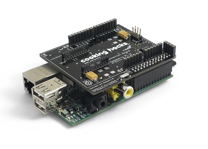
Raspberry Pi to Arduino Shield Connection Bridge
Puente para utilizar shields de Arduino en Raspberry Pi
COD: LIB88105
Peso: 0.050 Kg
Disponibilidad: En Stock
ARS 133783.00
El producto no está disponible para la venta en este momento
Características
The idea behind the Raspberry Pi to Arduino shields connection bridge is to allow to use any of the shields, boards and modules designed for Arduino in Raspberry Pi. It includes also the possibility of connecting digital and analog sensors, using the same pinout of Arduino but with the power and capabilities of Raspberry.
In order to make complete the compatibility we have created the arduPi library which allows to use Raspberry with the same code used in Arduino. To do so, we have implemented conversion functions so that you can control in the same way as in Arduino all the I/O interfaces:i2C, SPI, UART, analog, digital, in Raspberry Pi.
Let's summarize what we can do using this shield along with the arduPi library:
- Connect any Arduino Wireless module in Raspberry. Some examples: XBee 802.15.4/XBee ZigBee, RFID, NFC, Bluetooth, Bluetooth Pro, Wifi, GPRS, 3G
- Connect any sensor (analog 0-5V, digital) to Raspberry Pi with a precession of 16b using the ADC integrated. Connect also complex sensors through i2C and UART buses
- Connect any Arduino specific shield such as: Radiation sensor shield, CanBus, Relay shield,...
- Connect any electronic module or actuator which works over i2C, SPI, UART
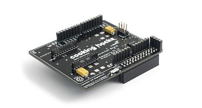
1. The Shield
Version 2 of the shield:
- This version includes a Digital Switch to enable/disable the socket for wireless modules using GPIO23 (Digital Pin 3).


Get the schematics here
Get the Raspberry Pi to Arduino shields connection bridge here.
Version 1 of the shield:
- 8 Digital pins.
- Socket for wireless modules.
- RX/TX pins.
- i2C pins (SDA, SCL).
- SPI pins (SCK, MISO, MOSI, CS). Can be used also as GPIO.
- 8 channel analog to digital converter.
- Switch to enable external power supply.


Get the schematics here
2. Modules and shields for Raspberry Pi
- Raspberry Pi to Arduino shields connection bridge
- GPRS/GSM Quadband Shield for Raspberry Pi [Tutorial]
- 3G + GPS Shield for Raspberry Pi [Tutorial]
- RFID 13.56 MHz/NFC shield for Raspberry Pi [Tutorial]
- RFID 125 KHz shield for Raspberry Pi [Tutorial]
- Wifi Module 'Roving RN-XV shield for Raspberry Pi' [Tutorial]
- XBee shield (802.15.4 / ZigBee) for Raspberry Pi [Tutorial]
- Bluetooth shield for Raspberry Pi [Tutorial]
- Bluetooth PRO shield for Raspberry Pi [Tutorial]
- GPS module shield for Raspberry Pi [Tutorial]
- Geiger Counter - Radiation Sensor Board for Raspberry Pi [Tutorial]


3. The library: arduPi
arduPi is a C++ library that lets you write programs for Raspberry Pi as if you were writing an arduino program. All the functions in order to control Serial port communications, i2C, SPI and GPIO pins are available using the arduino syntax.
arduPi has been tested in a Raspbian distribution. In order to write a Raspbian image to the SD card you can download the NOOBS hereand follow this instructions.
Once installed Raspbian, download and install arduPi library in a new folder, for example: "home/pi/ardupi"
For Raspberry Pi:
wget http://www.cooking-hacks.com/media/cooking/images/documentation/raspberry_arduino_shield/raspberrypi.zip && unzip raspberrypi.zip && cd raspberrypi && chmod +x compile_rpi && ./compile_rpi && cd ..
For Raspberry Pi 2:
wget http://www.cooking-hacks.com/media/cooking/images/documentation/raspberry_arduino_shield/raspberrypi2.zip && unzip raspberrypi2.zip && cd raspberrypi_2.0 && chmod +x compile_rpi2 && ./compile_rpi2 && cd ..
Download arduPi library for Raspberry Pi
Download arduPi library for Raspberry Pi 2
You can find a library changelog here.
General Arduino functions:
- delay()
- delayMicroseconds()
- millis()
- pinMode()
- digitalWrite()
- digitalRead()
- analogRead() (On pins from A0 to A7. Example: analogRead(5) will read from A5)
- shiftIn()
- shiftOut()
- attachInterrupt()*
- detachInterrupt()
[*] We can detect RISING and FALLING interrupts. Any digital pin (from 2 to 13) can be used in attachInterrupt(). For example if we want to be aware of RISING events on pin 6 we can do attachInterrupt(6,function_to_call,RISING).
- available()
- begin()
- end()
- flush()
- peek()
- print()
- println()
- read()
- readBytes()
- readBytesUntil()
- find()
- findUntil()
- parseInt()
- parseFloat()
- setTimeout()
- write()
- begin()
- requestFrom()
- beginTransmission()
- endTransmission()
- write()
- read()
- begin()
- end()
- setBitOrder()
- setClockDivider()
- setDataMode()
- transfer()
3.1 Using arduPi library:
In the library folder you will find 3 files: arduPi.cpp, arduPi.h and arduPi_template.cpp
The arduPi_template.cpp file is meant to be used as a starting point to create programs with the same behaviour as an arduino program.
Here you can see the template code:
//Include arduPi library
	#include "arduPi.h"

	/*********************************************************
	 *  IF YOUR ARDUINO CODE HAS OTHER FUNCTIONS APART FROM  *
	 *  setup() AND loop() YOU MUST DECLARE THEM HERE        *
	 * *******************************************************/

	/**************************
	 * YOUR ARDUINO CODE HERE *
	 * ************************/

	int main (){
		setup();
		while(1){
			loop();
		}
		return (0);
	}
As you can see in the main() function the setup() function is called once and then the loop() function is called continiously until the program is forced to finish.
Either if you are starting to write a new program, or if you have an arduino program written that uses the ported functions you can use the template (ardupi_template.cpp) and put your arduino code where it says: YOUR ARDUINO CODE HERE. Remember that the program you are writing is a C++ program so all the C++ libraries can be used.
Also remember, as you can read in the template that if your arduino code uses other functions apart from setup() and loop() you must declare them in the indicated area.
3.2 Enabling the UART port:
This steps are for new versions of Raspbian. We are going to turn off the UART as a serial console in order to let it available for us:
-
Enter in Raspberry Pi configuration:
sudo raspi-config -
Go to “Advanced Options”.
-
Select "Serial".
-
Select 'No' to disable shell and kernel messages via UART.
-
You will see "Serial is now disabled"->Ok->Finish to reboot.
The following steps are based on Raspbian Debian Wheezy 2015-02-16.
-
Open a terminal on the Raspberry Pi, or connect to Raspberry Pi through SSH.
-
Make a backup of the /boot/cmdline.txt file.
sudo cp /boot/cmdline.txt /boot/cmdline_backup.txt -
Open the file /boot/cmdline.txt:
sudo nano /boot/cmdline.txtThis file contains something similar to this (the content may vary):
dwc_otg.lpm_enable=0 console=ttyAMA0,115200 kgdboc=ttyAMA0,115200 console=tty1 root=/dev/mmcblk0p2 rootfstype=ext4 elevator=deadline rootwaitRemove the parameters that reference the UART serial port (ttyAMA0):
dwc_otg.lpm_enable=0 console=tty1 root=/dev/mmcblk0p2 rootfstype=ext4 elevator=deadline rootwait
-
Press CTRL+X to exit and save the file.
-
Open the file /etc/inittab:
sudo nano /etc/inittabFind this line (it should be at the end of the file):
T0:23:respawn:/sbin/getty -L ttyAMA0 115200 vt100Comment it with a “#” symbol in the beggining of the line:
#T0:23:respawn:/sbin/getty -L ttyAMA0 115200 vt100
-
Press CTRL+X to exit and save the file.
-
Reboot Raspberry Pi:
sudo reboot
We also recommend to enable SPI and I2C following these steps:
-
Enter in Raspberry Pi configuration:
sudo raspi-config -
Open “8 Advanced Options”.
-
Open “A6 SPI” and click “Yes” and “Ok” to all.
-
Repeat step 2 and then open “A7 I2C” and click “Yes” and “Ok” to all.
3.3 Compile arduPi library:
As arduPi is a C++ library we will use g++ to compile it. You can compile and download the arduPi library to obtain an object file (.o) and use this file to link your program:
For Raspberry Pi:
wget http://www.cooking-hacks.com/media/cooking/images/documentation/raspberry_arduino_shield/raspberrypi.zip && unzip raspberrypi.zip && cd raspberrypi && chmod +x compile_rpi && ./compile_rpi && cd ..
For Raspberry Pi 2:
wget http://www.cooking-hacks.com/media/cooking/images/documentation/raspberry_arduino_shield/raspberrypi2.zip && unzip raspberrypi2.zip && cd raspberrypi_2.0 && chmod +x compile_rpi2 && ./compile_rpi2 && cd ..
3.4 Compile a program that uses arduPi:
If you have already compiled the arduPi library (previous step) you can do:
g++ -lrt -lpthread MY_PROGRAM.cpp arduPi.o -o MY_PROGRAM
The -lrt flag is necesary because the library uses the function clock_gettime (time.h).
The -lpthread option is needed because attachInterrupt() and detachInterrupt() functions use threads.
3.5 Running your program
For running your program you must have the right permissions in order to use GPIO (/dev/mem needs to be accessed in the raspberry). You can run your program with sudo:
sudo ./MY_PROGRAM
4. Basic circuits.
Extreme caution when working with GPIO, you may damage your Raspberry Pi, your equipment and potentially yourself and others. Doing so is at your own risk!
More information:
http://elinux.org/RPi_Low-level_peripherals
http://elinux.org/RPi_Tutorial_EGHS:GPIO_Protection_Circuits
5.1 GPIO Input
GPIO peripherals vary quite widely. In some cases, they are very simple, a group of pins that can be switched as a group to either input or output. The input and output voltages are typically, though not universally limited to the supply voltage of the device with the GPIOs on, and may be damaged by greater voltages.
Some GPIOs have 5 V tolerant inputs: even on low supply voltages, the device can accept 5V without damage.
For Raspberry Pi, we present an examples of how to adapt the voltage level of a 5V sensor measure to prevent possible damage.
Components for this examples and voltage adaptation circuit can be founded in the Starter Kit for Raspberry Pi.
When a GPIO pin is set as an input with a basic push button example, we can have these voltages incompatibility problems.

This circuit is wrong because when you press the button the GPIO input is connected to 5 volts, so our device may be damaged.

However, this can be avoided by simply using a resistor in the push-button cable. The value of the resistor is determined by the leakage current of the GPIO pin (the current used by the circuit to read the pin) and the amount of voltage drop it creates as a result. With the 5K resistor we obtain 3.3V in the GPIO input.
Vgpio = 5V·(10K/(10K+5K)) = 3.3V
5.2 GPIO Sensor measurement
We will have the same problem if we use a sensor operating at 5 volts.
Here is an example using a PIR sensor.
As shown in the image, we use the same resistive divider used to adapt voltage level.

5. ADC.
The shield includes an ADC of 12b of resolution which allows to connect any sensor to Raspberry with higher precision that Arduino does. The communication between Raspberry and the ADC of the shield is made via i2C.
The information of each channel can be obtained reading two bytes from i2C, but previously one byte (corresponding to the channel address) should be send through i2C depending of the channel we want to select. Here is a list with the channel addresses:
| Channel | Adress |
| 0 | 0xDC |
| 1 | 0x9C |
| 2 | 0xCC |
| 3 | 0x8C |
| 4 | 0xAC |
| 5 | 0xEC |
| 6 | 0xBC |
| 7 | 0xFC |
Here is an example of a program that reads every channel continuously waiting 5 seconds between iterations.
With a wire connecting the 5V pin with some of the pins of the ADC a value near to 5.000000 should be read.
All the examples on this guide use the arduPi library.
Here is the output of this program connecting the 5V pin of Raspberry to the analog input 0:

6. UART.Go to index
Accessing the UART with arduPi library is as simple as doing it with Arduino.
You need to include arduPi.h in your code and create an instance of SerialPi class naming it Serial.
Naming the instance as Serial allows you to use the arduino syntax. (All this is allready done if you use the provided template to create your programs).
The functions available are:
- Serial.available()
- Serial.begin()
- Serial.end()
- Serial.flush()
- Serial.peek()
- Serial.print()
- Serial.println()
- Serial.read()
- Serial.readBytes()
- Serial.readBytesUntil()
- Serial.find()
- Serial.findUntil()
- Serial.parseInt()
- Serial.parseFloat()
- Serial.setTimeout()
- Serial.write()
All this functions have the same functionality as the arduino ones. You can find more information at:
http://arduino.cc/en/Reference/serial
An example of code that acess the UART can be found in the Raspberry Pi XBee tutorial
7. i2C.
An example of using i2C can be found on the ADC section.
Here we show another example using the BlinkM RGB i2C controlled led.

BlinkM uses a high quality, high power RGB LED and a small AVR microcontroller to allow a user to digitally control an RGB LED over a simple i2C interface.
In the example we will change the led color using fade transitions and also changing it directly. More information about the LED and the commands we can send to it can be found in the datasheet.
Connect the (-) pin of the led with the GND pin of the shield.
Connect the (+) pin of the led with the 5V pin of the shield.
Connect the d pin of the led with the SDA pin of the shield.
Connect the c pin of the led with the SCL pin of the shield.

Here is the code:
This code alternate from red to blue five times and then make some smooth transitions between purplish colors.

8. SPI.
It is possible to communicate with SPI devices using the functions provided by arduPi.
In this example we use the SPI functions for printing messages on the ST7920 LCD12864 (SPI LCD)
First of all, we need to put the switch of the LCD in SPI mode.
Now we proceed with the connection between the LCD and the Raspberry Pi to arduino shield :
VCC of the LCD to 5v of the shield
GND of the LCD to GND of the shield
SCK of the LCD to SCK of the shield
SID of the LCD to MOSI of the shield
CS of the LCD to 8 pin of the shield
As you can see we are using the pin number 8 of the Raspberry Pi shield as chip select. So when we need to select the LCD as the target device for the SPI communication we need to put the 8 pin to HIGH.

Here is the code:
This program will show the messages "Cooking Hacks" and "SPI LCD for Raspberry Pi" with a delay of 2 seconds in between.


9. Support.
Get help in the specific section created in our Forum.
10. Get the shield and kits.
Raspberry Pi kits
- Starter Kit for Raspberry Pi + Raspberry Pi
- Starter Kit for Raspberry Pi
- A/V Kit for Raspberry Pi + Raspberry Pi
- A/V Kit for Raspberry Pi
Raspberry Pi shields
- GPRS/GSM Quadband shield for Raspberry Pi
- 3G / GPRS shield for Raspberry Pi (3G+GPS)
- 3G / GPRS shield for Raspberry Pi (3G+GPS) + Audio/Video Kit
- RFID 13.56 MHz/NFC shield for Raspberry Pi
- RFID 125 KHz shield for Raspberry Pi
- Wifi shield for Raspberry Pi
- XBee shields for Raspberry Pi
- Bluetooth shield for Raspberry Pi
- Bluetooth PRO shield for Raspberry Pi
- GPS shield for Raspberry Pi
- Radiation shield for Raspberry Pi + Geiger Tube