Productos
5.0 Mega Pixel Banana PI Camera Module
Cámara de 5MP para Banana Pi
COD: FUT9034
Peso: 0.050 Kg
Disponibilidad: Sin Stock
ARS 51304.00
El producto no está disponible para la venta en este momento
Características
version 2.0 Banana PI Camera Module 5.0 Mega Pixel BPI Camera Module. OV5640 chipset, CSI connector
Applicable to:
-- BPI-M1 ;
-- BPI-M1+ ;
-- BPI-M2 ;
NOTE:
this camera can not be used for BPI-M3
![]()
Product Specifications:
|
Product Name |
Banana PI Camera Module v2.0 |
|
Product Description |
High definition camera module for BananaPi board via the CSI connector designed specifically for interfacing tocameras.Provide high sensitivity, low crosstalk and low noise image capture in a small and lightweight design. |
|
Image sensor |
Omnivision 5640 CMOS image sensor in a auto-fouces modules with integral IR filter (650±10nm) |
|
Still resolution |
5 Megapixels |
|
Active array size |
2592×1944 |
|
Max frame rate |
1080P 30fps@24Mhz |
|
Picture formats |
JPEG PNG YUV420 RGB888 |
|
Video formats |
Raw h.264 |
|
Connection to Banana Pi |
40 Pin FPC to the Camera Sensor Interface(CSI-0) |
|
Image control functions
|
Automatic exposure control (AEC) Automatic white balance(AWB) Automatic black level calibration(ABLC) Automatic band filter Mirror and flip |
|
Temp range
|
Operating: -30°C to 70°C Stable Image: 0°C to 50°C |
|
Lens size |
1/4″ |
|
Dimension |
36×32×10mm |
|
I2C address |
0x78 |
|
Weight |
8g |
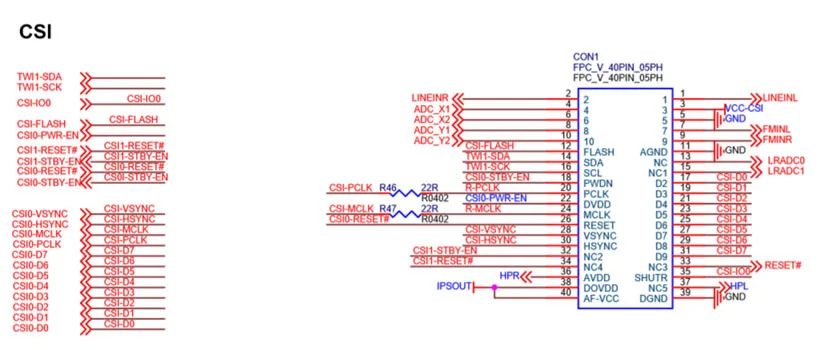
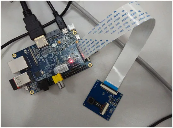
Banana pi CSI Camera Connector
The CSI Camera Connector is a 40-pin FPC connector which can connect external camera module with proper signal pin mappings.
Use Camera on Android4.2
The Android4.2 system for BPI has a Camera app, it can be used easily.
1. Click the Applications icon.
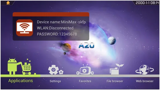
2. Choose the Camera application.

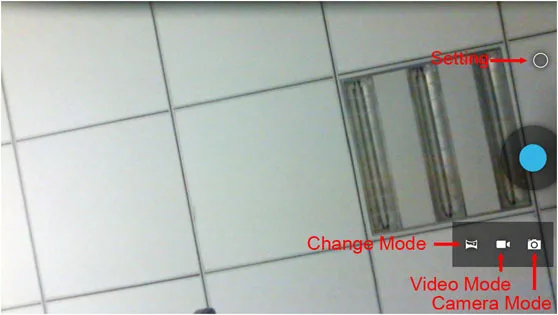
3. Photo Mode.
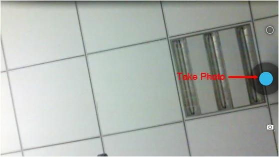
4. Setting Icons and Change Mode Icons.
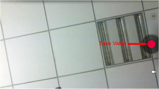
5. Video Mode.
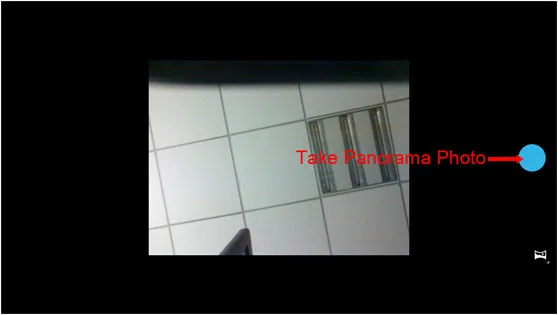
6. Panorama Mode.
More informatin:
If you want to porting the camera ov5640 driver on others system.Here are some information you may need.
CON1 Mapping:
|
CSI Pin |
Pin Name |
GPIO |
|
CON1 P01 |
LINEINL |
|
|
CON1 P02 |
LINEINR |
|
|
CON1 P03 |
VCC-CSI |
|
|
CON1 P04 |
ADC_X1 |
|
|
CON1 P05 |
GND |
|
|
CON1 P06 |
ADC_X2 |
|
|
CON1 P07 |
FMINL |
|
|
CON1 P08 |
ADC_Y1 |
|
|
CON1 P09 |
FMINR |
|
|
CON1 P10 |
ADC_Y2 |
|
|
CON1 P11 |
GND |
|
|
CON1 P12 |
CSI-FLASH |
PH17 |
|
CON1 P13 |
LRADC0 |
|
|
CON1 P14 |
TWI1-SDA |
PB19 |
|
CON1 P15 |
LRADC1 |
|
|
CON1 P16 |
TWI1-SCK |
PB18 |
|
CON1 P17 |
CSI-D0 |
PE4 |
|
CON1 P18 |
CSI0-STBY-EN |
PH19 |
|
CON1 P19 |
CSI0-D1 |
PE5 |
|
CON1 P20 |
CSI-PCLK |
PE0 |
|
CON1 P21 |
CSI-D2 |
PE6 |
|
CON1 P22 |
CSI0-PWR-EN |
PH16 |
|
CON1 P23 |
CSI-D3 |
PE7 |
|
CON1 P24 |
CSI0-MCLK |
PE1 |
|
CON1 P25 |
CSI-D4 |
PE8 |
|
CON1 P26 |
CSI0-RESET# |
PH14 |
|
CON1 P27 |
CSI-D5 |
PE9 |
|
CON1 P28 |
CSI-VSYNC |
PE3 |
|
CON1 P29 |
CSI-D6 |
PE10 |
|
CON1 P30 |
CSI-HSYNC |
PE2 |
|
CON1 P31 |
CSI-D7 |
PE11 |
|
CON1 P32 |
CSI1-STBY-EN |
PH18 |
|
CON1 P33 |
RESET# |
|
|
CON1 P34 |
CSI1-RESET# |
PH13 |
|
CON1 P35 |
CSI-IO0 |
PH11 |
|
CON1 P36 |
HPR |
|
|
CON1 P37 |
HPL |
|
|
CON1 P38 |
IPSOUT |
|
|
CON1 P39 |
GND |
|
|
CON1 P40 |
IPSOUT |
|