Productos
VNH2SP30 Motor Driver Carrier MD01B
Driver para un motor DC de 5.5V a 16V, con una capacidad de corriente de 14 Amper, diseñado y fabricado por Pololu
COD: P000706
Peso: 0.001 Kg
Disponibilidad: Sin Stock
ARS 64146.00
El producto no está disponible para la venta en este momento
Características
This carrier board for ST's VNH2SP30 motor driver IC operates from 5.5 to 16 V and can deliver a continuous 14 A (30 A peak). It works with 5 V logic levels, supports ultrasonic (up to 20 kHz) PWM, and features current sense feedback (an analog voltage proportional to the motor current). Along with built-in protection against reverse-voltage, over-voltage, under-voltage, over-temperature, and over-current, these features make this product a great general-purpose motor driver.
Overview
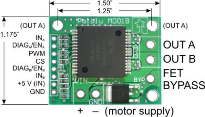 |
| Pololu High-Current Motor Driver Carrier pinouts and dimensions. |
|---|
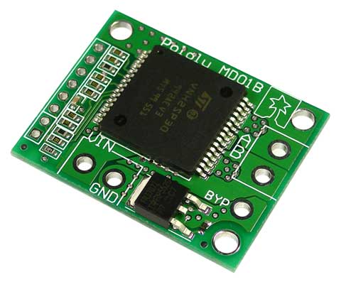
This module is a compact breakout board for ST's high-power VNH2SP30 motor driver IC, which is a fully integrated H-bridge that can be used for bidirectional speed control of a single brushed DC motor. The basic operation of the driver is summarized below, but we also recommend careful reading of the VNH2SP30 datasheet (228k pdf) before using this product. The board incorporates most of the components of the typical application diagram on page 8 of the VNH2SP30 datasheet, including pull-up and current-limiting resistors and a FET for reverse battery protection. It ships fully populated with its SMD components, including the VNH2SP30 motor driver IC, as shown in the product picture.
In a typical application, the motor power supply is connected at the bottom of the board, the motor on the right side of the board, and the control connections to the left side of the board. The diagnostic/enable pins are pulled high on the board and can be left disconnected if you do not want to monitor the fault conditions of the motor driver chip. INA and INB control the direction of the motor, and the PWM pin turns the motor outputs on or off, allowing you to control motor speed with a supplied pulse width modulation (PWM) signal. The PWM pin is pulled low on the board, so the motor driver outputs are effectively disabled by default; the INA and INB pins are floating (they are not pulled to any particular default voltage). See the truth tables in the VNH2SP30 datasheet for more information on how the INA, INB, and PWM pins affect the driver outputs, OUTA and OUTB.
The current sense (CS) pin will output approximately 0.13 volts per amp of output current.
Note: An 8-pin 0.1" male header and two 2-pin terminal blocks are included but not soldered onto the boards. You can solder these in yourself and use this board with custom cables or solderless breadboards, or you can solder wires directly to the board for more compact installations.
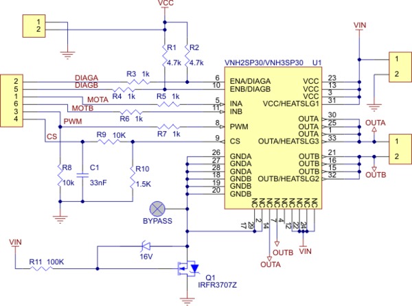
 |
| Schematic of the Pololu High Current Motor Driver Carrier |
|---|
Warning: The top two mounting holes on this carrier board are electrically connected to the OUTA node in an effort to increase thermal dissipation. Please be aware of this if you are mounting more than one of these carrier boards to a metal structure using metal fasteners, or if you are mounting one of these carrier boards to a grounded structure using metal fasteners, as this could cause you to unintentionally short out your power supply. You can avoid the problem in such situations by avoiding those mounting holes or by using non-conducting mounting hardware, such as nylon screws.
Reverse-battery protection
The motor driver boards include an N-channel MOSFET for reverse-battery protection. This component keeps the motor driver from destroying itself if the input power is accidentally connected backwards. However, this component does slightly increase the total resistance between your battery and your motor. For slightly improved performance, the MOSFET can be bypassed by connecting the negative battery terminal to the bypass pin. (This terminal will also need to be connected to your logic supply ground.)
Dimensions
| Size: | 1.50" x 1.18" |
|---|
General specifications
| Motor driver: | VNH2SP30 |
|---|---|
| Motor channels: | 1 |
| Minimum operating voltage: | 5.5 V |
| Maximum operating voltage: | 16 V |
| Continuous output current per channel: | 14 A |
| Peak output current per channel: | 30 A |
| Current sense: | 0.13 V/A |
| Maximum PWM frequency: | 20 kHz |
| Reverse voltage protection?: | Y |