Productos
SMA Female with PCB Mount 11mm 50 OHM RF Connector

OFERTA POR RENOVACION DE STOCK!!! Conector SMA de 50 ohm tipo hembra para montaje en placa. Muy utilizado en telecomunicaciones, control de procesos, instrumentación, etc.
COD: HTHR0672-U
Peso: 0.003 Kg
Disponibilidad: En Stock
ARS 990.00
El producto no está disponible para la venta en este momento
Características
DESCRIPTION:
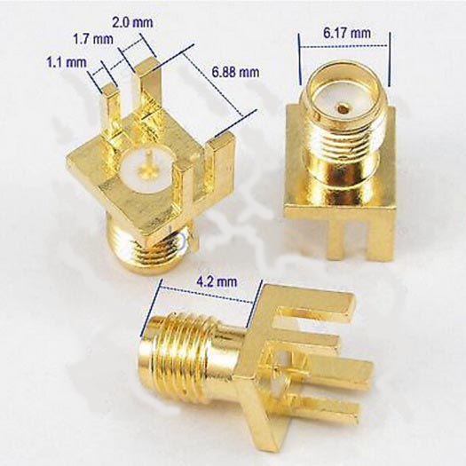
- Item Name: SMA Female Connector with PCB Mount (SMA-KE).
- Connector: SMA Female (outer hole).
- Characteristic Impedance : 50Ω.
- Length:11mm.
SMA CONNECTOR SERIES:
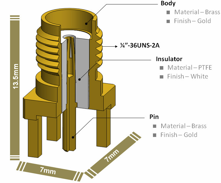
Using a threaded interface, SMA 50 Ohm connectors are semi-precision units that provide excellent electrical performance from DC to 18 GHz and outstanding mechanical durability. SMA connectors feature stainless steel or brass construction and ¼ - 36 threaded coupling, which offers high performance in a compact design.
For phase array radar, test equipment, ILS landing systems and other instrumentation using phase matching techniques, SMA interconnects offer a precise and simple means of phase adjustment for microwave devices. Built in accordance with MIL-C-39012 and CECC 22110/111, SMA connectors can be mated with all connectors that meet these specification mating diameters regardless of manufacturer.
FEATURES AND BENEFITS:
- Light weight, compact and vibration proof design.
- Low cost commercial grade (Brass SMA) available in nickel or gold plating.
- Terminates to all standard flexible coaxial cables, low-loss (LMR) type cables and industry standard semi-rigid and conformable cables.
APPLICATIONS:
- Base stations.
- Antennas.
- Telecommunications.
- Instrumentation.
- PC/LAN.
SMA SPECIFICATIONS:
| Electrical | |
| Impedance | 50 Ohm |
| Frequency Range | |
| .141" & .085" O.D. Copper Jacket Semi-Rigid Cable | 0-18 GHz |
| Flexible Cables | 0-12.4 GHz |
| Voltage Rating | |
| RG-55, 58, 141, 142, 223, 303 | 500 volts peak |
| RG-122, 174, 188, 316 | 375 volts peak |
| Dielectric Withstanding Voltage (max.) | |
| .141" & RG-58 Group | 1000 VRMS |
| .085" & RG-316 Group | 750 VRMS |
| VSWR for Straight Connectors | |
| .141" O.D. Copper Jacket Cable | 1.05 + .005 f (GHz) |
| RG-55 Group | 1.15 + .011 f (GHz) |
| RG-122 Group | 1.15 + .02 f (GHz) |
| RG-178 Group | 1.20 + .025 f (GHz) |
| VSWR for Angle Connectors | |
| .141" O.D. Copper Jacket Cable | 1.10 + .01 f (GHz) |
| RG-55 Group | 1.15 + .02 f (GHz) |
| RG-122 Group | 1.15 + .03 f (GHz) |
| RG-178 Group | 1.20 + .03 f (GHz) |
| Insulation Resistance | 5000 Mohms |
| Contact Resistance | |
| Center Conductor | 2.0 mohms |
| Body | 2.0 mohms |
| Braid to Body | 0.5 mohms |
| RF Leakage | -60 dB min |
| Insertion Loss | .03 sqrt(f(GHz)) dB max |
| Environmental | |
| Temperature Range | -65⁰C to +165⁰C |
| Thermal Shock | MIL-STD-202 Method 107 (test cond. B) except at high temp test @ + 200⁰C |
| Corrosion | MIL-STD-202 Method 101 (test cond. B) 5% salt solution |
| Vibration | MIL-STD-202 Method 204 (test cond. D) |
| Shock | MIL-STD-202 Method 213 (test cond. I) No Discontinuity Permitted |
| Moisture Resistance | MIL-STD-202 Method 106, except step 7b (vibration) omitted, and high humidity measurements do not apply |
| Weatherproofing | |
| Crimp Type | heat shrink tubing |
| Solder Type | Silicone rubber gaskets |
| Altitude | MIL-STD-202 Method 105 (test cond. C), no corona at 70,000 ft |
| .141" & RG-55 Group | 250 WRMS |
| .085" & RG-122 Group | 190 VRMS |
| Mechanical | |
| Contact Captivation | All types, except as noted |
| Connector Durability | 500 mating and unmating cycles @ 12 cycles/min |
| Cable Retention | |
| RG-58, .141, 303 | Crimp type, 60 lbs min |
| RG-55, 142, 223 | 80 lbs min, 400 N.cm |
| Connector Affixment to Cable | Crimp types, solder types |
| Connector Affixment to Center Contact | Solder, except as noted |
| Mating | .250-36 threaded coupling |
| Mating Torque | |
| Minimum | 2" lb, 22 N.cm |
| Recommended (Industrial/Military Grade Parts) | 7-10" Ib, 80-110 N.cm |
| Recommended (Commercial Grade Parts) | 4-6"lb, 45-67 N.cm |
| Maximum (Industrial/Military Grade only) | 15" lb, 170N.cm |
| Coupling Nut Retention | |
| Axial Force | 100lbs. Min., 300N.cm |
| Torque | 15" lb min. 76 N.cm |
| Jacks | N/A |
REVERSE POLARITY SMA SPECIFICATIONS:
| Electrical | |
| Impedance | 50 Ohm |
| Frequency Range | |
| Semi-Rigid | 0-18 GHz |
| Flexible Cables | 0-12.4 GHz |
| VSWR | |
| Straight Connectors: .141" S/R | 1.05 + .005 f (GHz) |
| Straight Connectors: RG-174 | 1.20 + .025 f (GHz) |
| Dielectric Withstanding Voltage | 1000 VRMS |
| Insertion Loss | .03 sqrt(f(GHz)) dB max |
| Insulation Resistance | 5000 M�?� |
| RF Leakage | -60 dB min |
| Voltage Rating | 375 volts peak |
| Environmental | |
| Temperature Range | -65⁰C to +165⁰C |
| Moisture Resistant | Mil-STD-202, Method 106 (test cond. B) |
| Corrosion | Mil-STD-202, Method 101, Condition B |
| Vibration | Mil-STD-202, Method 204, Condition B |
| Mechanical | |
| Mating | .250-36 threaded coupling |
| Cable Affixment | Crimp or solder types |
| Center Conductor | Solder |
| Cable Retention | 60- 80 lb, depending on cable |
INTERFACE DIMENSIONS:

Package Included:
- 1 x SMA Female Connector with PCB Mount (SMA-KE)