Productos
Micro:bit expansion board and Breakout adapter board
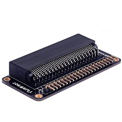
OFERTA POR RENOVACION DE STOCK!!! Placa de expansión para la micro:bit. Permite acceder cómodamente a todos sus pines!. Dispone de un zócalo para inserción.
COD: OKY900B
Peso: 0.025 Kg
Disponibilidad: En Stock
ARS 4990.00
El producto no está disponible para la venta en este momento
Características
Description:
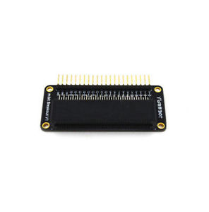
Looking to do more with your BBC micro:bit? Unlock its potential with this pre-built version of our Edge Connector Breakout Board! This breakout board has been designed to offer an easy way to connect additional circuits and hardware to the pins on the edge of the BBC micro:bit. It provides access to all of the BBC micro:bit processor pins allowing a lot of extra functionality to be added. The datasheet (below) includes a helpful diagram explaining the function of every pin on the BBC micro:bit.
This Edge Connector Breakout Board for the BBC micro:bit gives access to all of the important pins on the bottom edge of the BBC micro:bit. 21 pins are broken out in total; providing additional I/O lines, direct access to buttons A and B, the LED matrix outputs and the I2C bus. Please refer to the datasheet below for more details.
The BBC micro:bit pins are broken out to a row of pin headers. These provide an easy way of connecting circuits using jumper wires. The SCL and SDA pins are separated at the edge of the board (solder pads) providing easy identification. The PCB includes a prototyping area with 3V, 0V and unconnected rows that can be soldered to. This allows the easy connection of switches, sensors and any pull-up or pull-down resistors etc. as required.
Specifications:
There are 20 small pins numbered sequentially from 3-22.
Unlike the three large pins that are dedicated to being used for external connections, some of the small pins are shared with other components on the BBC micro:bit board. For example, pin 3 is shared with some of the LEDs on the screen of the BBC micro:bit, so if you are using the screen to scroll messages, you can’t use this pin as well.
- pin 3: GPIO shared with LED Col 1 of the LED screen; can be used for ADC and digital I/O when the LED screen is turned off.
- pin 4: GPIO shared with LED Col 2 of the LED screen; can be used for ADC and digital I/O when the LED screen is turned off.
- pin 5: GPIO shared with Button A. This lets you trigger or detect a button "A" click externally. This pin has a pull-up resistor, which means that by default it is at voltage of 3V. To replace button A on the BBC micro:bit with an external button, connect one end of the external button to pin 5 and the other end to GND. When the button is pressed, the voltage on pin 5 is pulled down to 0, which generates a button click event.
- pin 6: GPIO shared with LED Col 9 of the LED screen; can be used for digital I/O when the LED screen is turned off.
- pin 7: GPIO shared with LED Col 8 of the LED screen; can be used for digital I/O when the LED screen is turned off.
- pin 8: Dedicated GPIO, for sending and sensing digital signals.
- pin 9: GPIO shared with LED Col 7 of the LED screen; can be used for digital I/O when the LED screen is turned off.
- pin 10: GPIO shared with LED Col 3 of the LED screen; can be used for ADC and digital I/O when the LED screen is turned off.
- pin 11: GPIO shared with Button B. This lets you trigger or detect a button “B” click externally.
- pin 12: Dedicated GPIO, for sending and sensing digital signals.
- pin 13: GPIO that is conventionally used for the serial clock (SCK) signal of the 3-wire Serial Peripheral Interface (SPI) bus.
- pin 14: GPIO that is conventionally used for the Master In Slave Out (MISO) signal of the SPI bus.
- pin 15: GPIO that is conventionally used for the Master Out Slave In (MOSI) signal of the SPI bus.
- pin 16: Dedicated GPIO (conventionally also used for SPI ‘Chip Select’ function).
- pins 17 and 18: these pins are wired to the 3V supply, like the large ‘3V’ pad.
- pins 19 and 20: implement the clock signal (SCL) and data line (SDA) of the I2C bus communication protocol. With I2C, several devices can be connected on the same bus and send/read messages to and from the CPU. Internally, the accelerometer and the compass are connected to i2c.
- pins 21 and 22: these pins are wired to the GND pin and serve no other function.
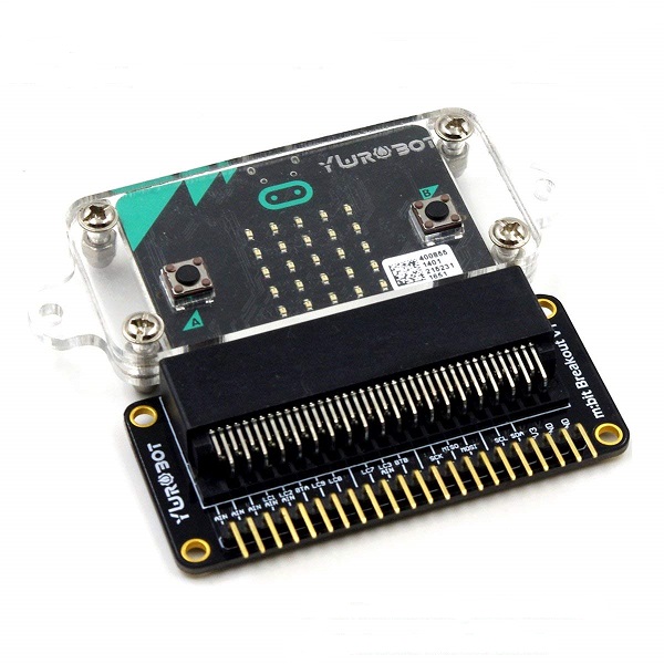
To use the breakout board the BBC micro:bit should be inserted firmly into the connector as shown below: