Productos
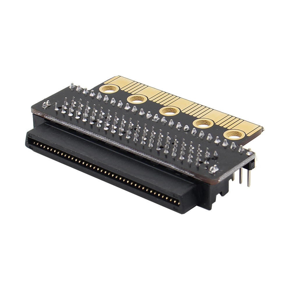
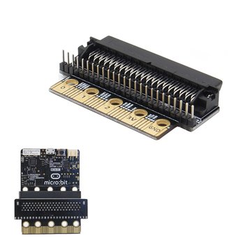
micro:bit GPIO expansion board
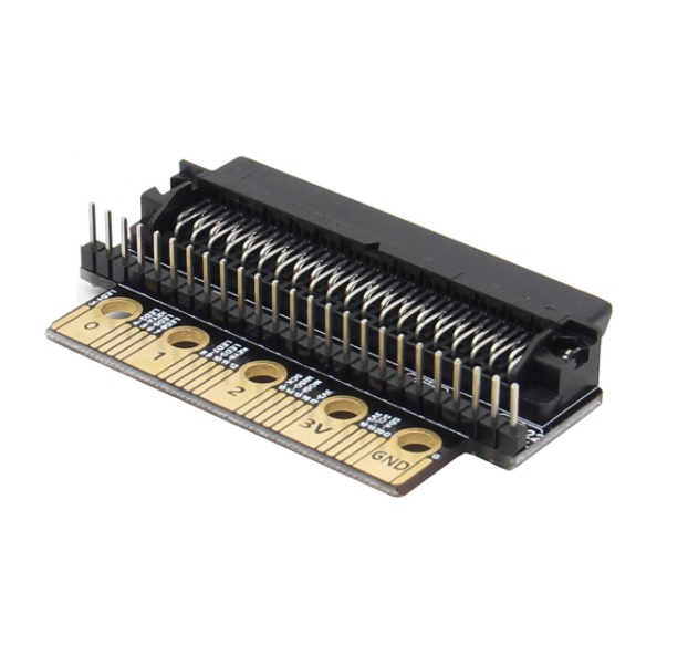
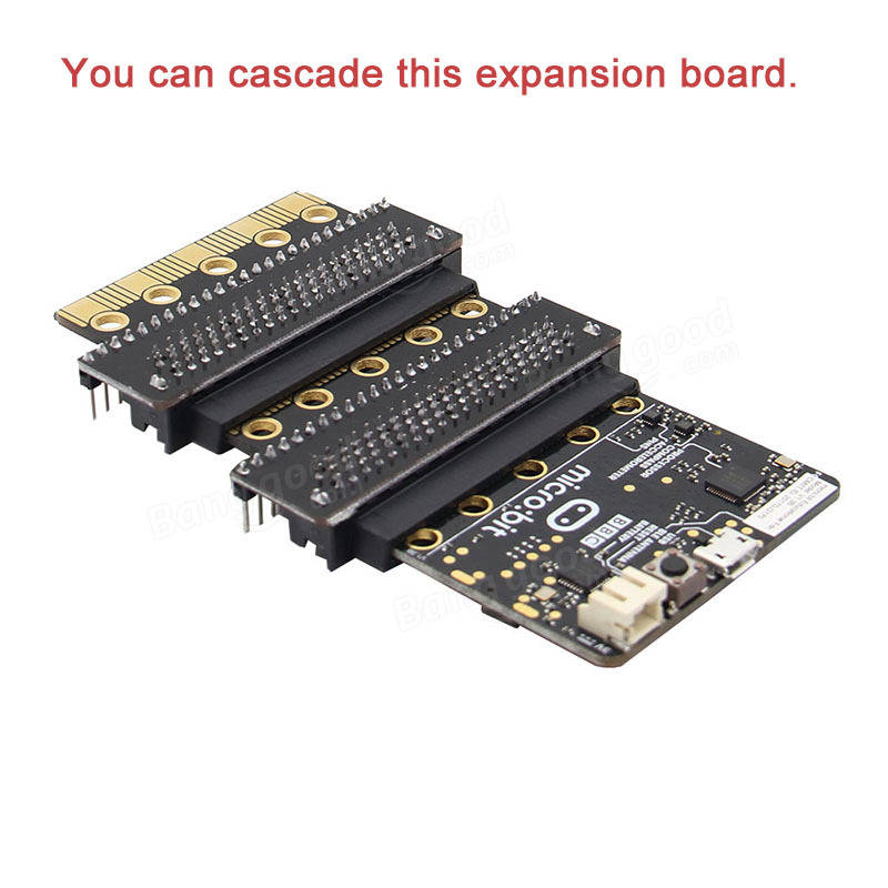
OFERTA POR RENOVACION DE STOCK!!! Placa de expansión para la micro:bit. Permite acceder cómodamente a todos sus pines!. Posee un zócalo de inserción, ofrece la posibilidad de conexión en cascada.
COD: OKY900B-2
Peso: 0.035 Kg
Disponibilidad: En Stock
ARS 4990.00
El producto no está disponible para la venta en este momento
Características
Description:
This is a GPIO expansion board for Micro: bit, it’s convenient to operate. It can be inserted the expansion board directly into the Micro: bit, and this expansion board can be cascaded.
Specifications:
There are 20 small pins numbered sequentially from 3-22.
Unlike the three large pins that are dedicated to being used for external connections, some of the small pins are shared with other components on the BBC micro:bit board. For example, pin 3 is shared with some of the LEDs on the screen of the BBC micro:bit, so if you are using the screen to scroll messages, you can’t use this pin as well.
- pin 3: GPIO shared with LED Col 1 of the LED screen; can be used for ADC and digital I/O when the LED screen is turned off.
- pin 4: GPIO shared with LED Col 2 of the LED screen; can be used for ADC and digital I/O when the LED screen is turned off.
- pin 5: GPIO shared with Button A. This lets you trigger or detect a button "A" click externally. This pin has a pull-up resistor, which means that by default it is at voltage of 3V. To replace button A on the BBC micro:bit with an external button, connect one end of the external button to pin 5 and the other end to GND. When the button is pressed, the voltage on pin 5 is pulled down to 0, which generates a button click event.
- pin 6: GPIO shared with LED Col 9 of the LED screen; can be used for digital I/O when the LED screen is turned off.
- pin 7: GPIO shared with LED Col 8 of the LED screen; can be used for digital I/O when the LED screen is turned off.
- pin 8: Dedicated GPIO, for sending and sensing digital signals.
- pin 9: GPIO shared with LED Col 7 of the LED screen; can be used for digital I/O when the LED screen is turned off.
- pin 10: GPIO shared with LED Col 3 of the LED screen; can be used for ADC and digital I/O when the LED screen is turned off.
- pin 11: GPIO shared with Button B. This lets you trigger or detect a button “B” click externally.
- pin 12: Dedicated GPIO, for sending and sensing digital signals.
- pin 13: GPIO that is conventionally used for the serial clock (SCK) signal of the 3-wire Serial Peripheral Interface (SPI) bus.
- pin 14: GPIO that is conventionally used for the Master In Slave Out (MISO) signal of the SPI bus.
- pin 15: GPIO that is conventionally used for the Master Out Slave In (MOSI) signal of the SPI bus.
- pin 16: Dedicated GPIO (conventionally also used for SPI ‘Chip Select’ function).
- pins 17 and 18: these pins are wired to the 3V supply, like the large ‘3V’ pad.
- pins 19 and 20: implement the clock signal (SCL) and data line (SDA) of the I2C bus communication protocol. With I2C, several devices can be connected on the same bus and send/read messages to and from the CPU. Internally, the accelerometer and the compass are connected to i2c.
- pins 21 and 22: these pins are wired to the GND pin and serve no other function.
Package list:
- Micro: bit GPIO expansion board x 1.
- Size: 64 x 37 x 12 mm.