Productos
38 kHz IR Proximity Sensor (High Brightness)
Sensor de proximidad infrarrojo de alto brillo modulado en 38 Khz para sensado de hasta 60 cm de distancia.
COD: P002460
Peso: 0.005 Kg
Disponibilidad: Sin Stock
ARS 13865.00
El producto no está disponible para la venta en este momento
Características
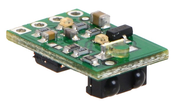
This module features a fixed-gain, 38 kHz modulated IR sensor and a corresponding IR LED with oscillator circuit to make a tiny proximity sensor. This high-brightness version draws an average of 16 mA and has a typical sensing range up to approximately 24 inches (60 cm).
Overview
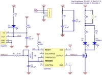
These sensor modules are based on Vishay’s TSSP77038 modulated infrared receivers. Unlike most IR receiver modules designed for remote control of appliances like televisions, the TSSP77038 has a fixed gain (sensitivity) that makes the sensor more predictable when used in proximity or reflectance sensors. The Pololu carrier module combines the TSSP77038 with an IR LED driven by a 555 timer-based circuit to make a complete sensor module that requires only a 3.3 V to 5 V power connection. An enable input allows control of whether or not the IR LED is on, and a digital output indicates whether or not an object is detected.
Using the sensor
Connections
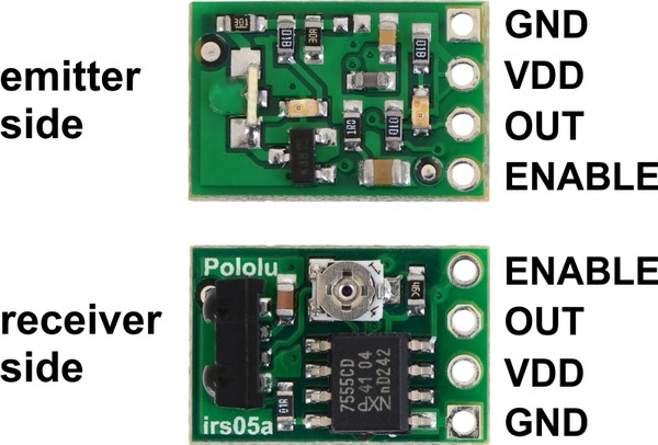
The proximity sensor has four connections: ground (GND), logic power (VDD), digital detection indicator (OUT), and IR emitter enable (ENABLE).
The logic power, VDD, should be between 3.3 V and 5 V. Supplying less than 5 V will decrease the IR LED brightness and decrease the sensing range. To run the sensor at full brightness while powered at 3.3 V, bridge the surface mount jumper located on the emitter side of the board.
The OUT pin, which is high by default, remains low as long as the TSSP77038 receiver is detecting a sufficient signal. When at the edge of the detection range, this output will alternate between high and low. A red LED on the emitter side of the board is tied to this output and turns on when the pin goes low, providing a visual indication of when the sensor is detecting something.
The ENABLE pin turns off the IR emitter LED when it is set low. This pin is high by default and can be left disconnected if dynamic control of the IR emitter is not needed. A green LED on the emitter side of the board is connected in parallel with the IR LED, making it easy to tell when the IR LED is on.
Tuning the emitter frequency
The trimmer potentiometer on the receiver side of the sensor can be used to adjust frequency of the IR emitter LED. The sensing distance can be maximized by tuning for 38 kHz, or it can be intentionally detuned to shorten the sensing range. If you have the appropriate equipment, you can tune it by setting the actual frequency, but a simpler approach is to just observe the performance as you turn the pot. The sensor should work to at least some degree over the entire range of the pot.
Limitations
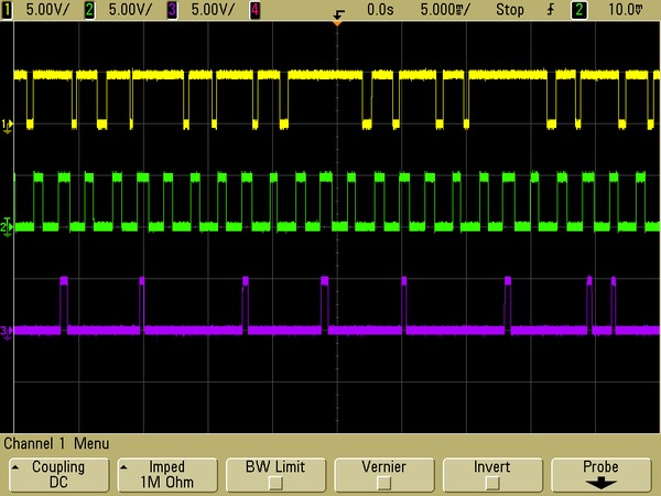
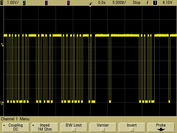
- This sensor will only tell you if an object is within its sensing range, not how far away it is. At the edge of its detection range, the output will alternate between high and low as it sporadically detects (see the left oscilloscope capture below).
- The sensor is merely looking at whether or not it is getting any signal back, so object size and reflectivity (to IR) will affect sensing range.
- The sensing angle is relatively wide in both directions. The high-brightness version in particular might require extra consideration when mounting to prevent seeing surfaces parallel to the sensor’s line of sight. For many applications, additional shielding can be used to block undesirable sensing paths, such as reflections off of the ground, or to reduce interference from ambient lighting. When applying shielding, keep in mind that reflection off the shielding itself can cause undesired activation of the sensor.
- This sensor can be triggered by ambient IR (e.g. from fluorescent lights; see the right oscilloscope capture below). Some optical shielding, such as by having the sensor mounted receiver-side-down when fluorescent lights are above, might mitigate this. Some advanced analysis of the correlation between the output and toggling of the enable input might also be used to mitigate ambient interference.
- Multiple sensors can interfere with each other. Multi-module applications might require use of the enable inputs to limit interference.