Productos
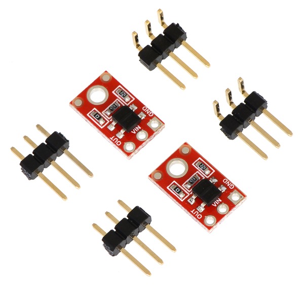
QTR-1A Reflectance Sensor (2-Pack)
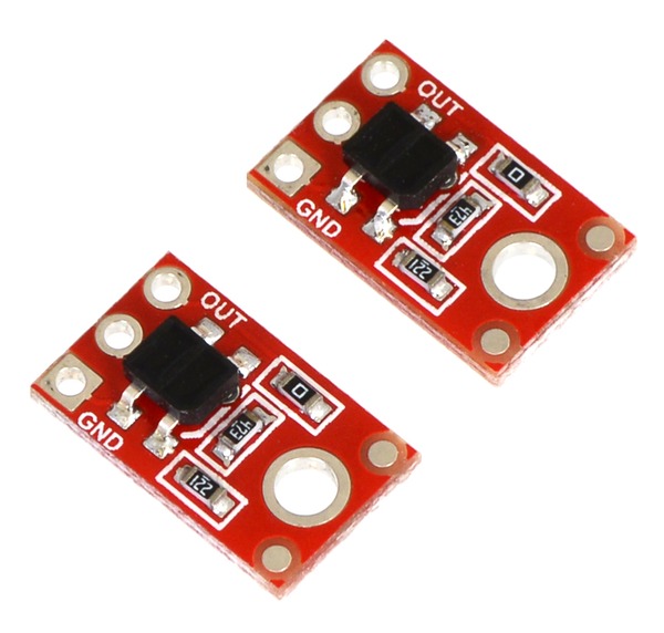
Par de sensores de reflectancia analógicos, ideales para detección de bordes o para seguimiento de línea.
COD: P002458
Peso: 0.010 Kg
Disponibilidad: Sin Stock
ARS 10102.00
El producto no está disponible para la venta en este momento
Características
The QTR-1A reflectance sensor carries a single infrared LED and phototransistor pair in an inexpensive, tiny 0.5" x 0.3" module that can be mounted almost anywhere and is great for edge detection and line following. The reflectance measurement is output as an analog voltage. This sensor is sold in packs of two units.
Functional Description
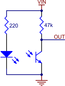
The Pololu QTR-1A reflectance sensor carries a single infrared LED and phototransistor pair. The phototransistor is connected to a pull-up resistor to form a voltage divider that produces an analog voltage output between 0 V and VIN (which is typically 5 V) as a function of the reflected IR. Lower output voltage is an indication of greater reflection.
The LED current-limiting resistor is set to deliver approximately 17 mA to the LED when VIN is 5 V. The current requirement can be met by some microcontroller I/O lines, allowing the sensor to be powered up and down through an I/O line to conserve power.
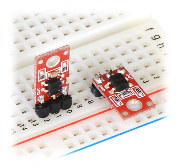
This sensor was designed to be used with the board parallel to the surface being sensed. Because of its small size, multiple units can easily be arranged to fit various applications such as line sensing and proximity/edge detection.
Specifications
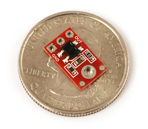
- Dimensions: 0.3" x 0.5" x 0.1" (without optional header pins installed)
- Operating voltage: 5.0 V
- Supply current: 17 mA
- Output format: analog voltage
- Output voltage range: 0 to supplied voltage
- Optimal sensing distance: 0.125" (3 mm)
- Maximum recommended sensing distance: 0.25" (6 mm)
- Weight without header pins: 0.008 oz (0.2 g)
Interfacing with the QTR-1A Output
There are several ways you can interface with the QTR-1A output:
- Use a microcontroller’s analog-to-digital converter (ADC) to measure the voltage.
- Use a comparator with an adjustable threshold to convert the analog voltage into a digital (i.e. black/white) signal that can be read by the digital I/O line of a microcontroller.
- Connect the output directly to the digital I/O line of a microcontroller and rely upon its internal comparator.